If you’re like me – a real newbie to Radio Control – then stick with me as I try and explain a few things and show how I added RC to this model. If this is all old-hat to you, then you can always point out only glaring mistakes I make… I’m always eager to learn.
My Starting Point
If you've seen my caterpillar tracks you'll see that they are driven by two brushed DC motors, one for each track. So this was my starting point... I needed to be able to control the speed and direction of two motors individually.
But what was necessary? What was required? What’s needed for a basic radio control setup?
A Basic Radio Control Set Up
Let's begin with a brief introduction to the necessary components in a Radio Control (RC) set up beginning with the most obvious one...
The Transmitter
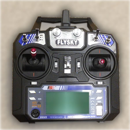
I think most people realise there's a transmitter involved, and even if they don't know what it is, or what it does, they've seen them - hand-held devices like the one shown at the beginning of this page.
The transmitters is a control boxes. It takes the instructions the user inputs via control sticks or switches and encodes these into radio frequency, transmitting this information up to several thousand times a second.
Transmitter Channels
Transmitters have channels and each channel can be thought of as an ability to do something, so more channels equates to being able to do more things.
Receiver
Next comes the Receiver. The Transmitter and Receiver are bound to each other. Theoretically this stops them from being accidentally influencing other Radio Control devices in the same locality.
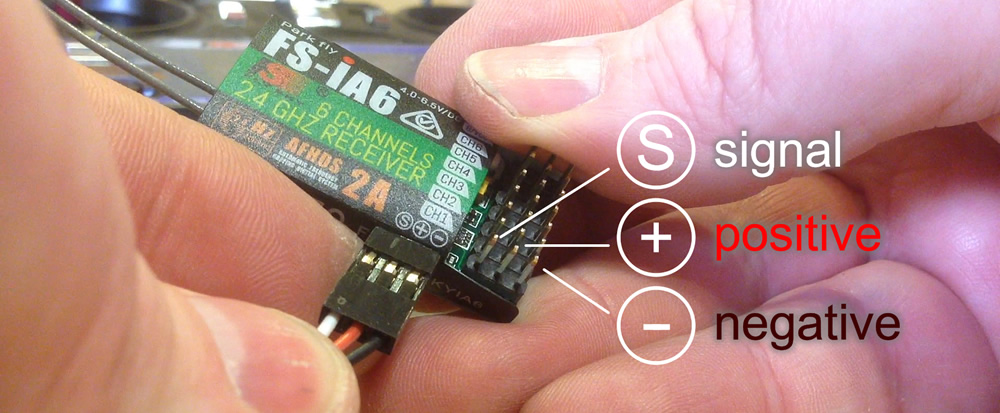
Receiver - surprisingly small but capable of receiving multiple channels of information - each channel have a row of pins and each pin having a specific polarity. Sounds tricky but it's just a case of plugging the right connection onto the right channel.
The receiver usually sits inside the device that’s being controlled (like a model plane or car) and as the name suggests, it listens out for instructions which it then passes to the actual ‘doing’ components, like servos and motor controllers.
The Receiver has a series of pins which are connected to these other items using the servo cables. It’s important to take careful note of the polarity… get these the wrong way round and you could damage your equipment.
Servos
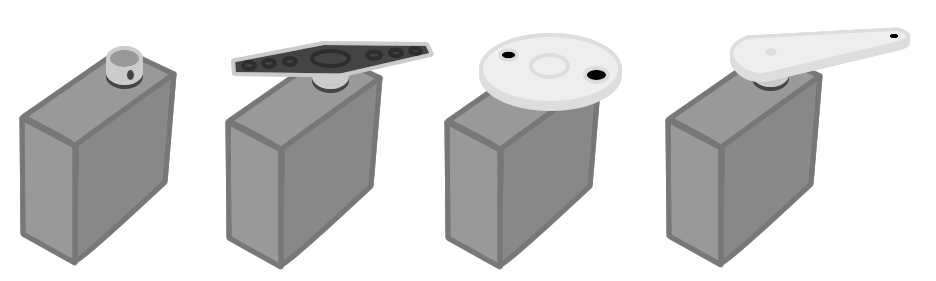
Servos take the electronic signal and translate this into mechanical movement, usually in the form of a rotating arm.
Servos - usually containing small motors and gears, there's a massive variety of shapes, sizes and functions
There’s a massive variety of these but I won’t be using any here but they’re so important to RC model making, I just had to give them a mention.
Motor Speed Controller
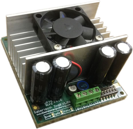
Again as the name suggests, a speed controller safely varies the speed of your motors in accordance with your instructions, but this is much more involved than may be realised.
Motor Speed Controller - this is a Sabertooth 2x60 Dual controller
Large, heavy duty motors in particular draw a lot of electrical power, more than enough to fry the average human. Starting from stand-still, there’s often a surge of power that can be ten or twenty times the usual power drain. Then there’s rapid speed changes and of course direction changes, which literally send the motors into a spin. All of this invariably draws massive amounts of power that could potentially damage your motors. So the speed controller handles this safely, typically turning the motors on and off thousands of times each second, which maintains momentum but reduces power usage, safely converting excess power to heat.
For me the speed controller was the most expensive component and that should give you a good idea of its importance. Don't undervalue them!
RC Recap
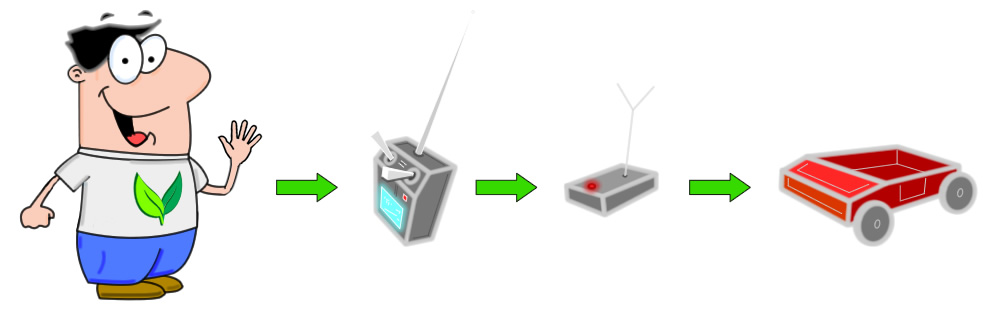
So a quick recap…
You tell the transmitter what you want your device to do using its controls.
The transmitter sends this information to the receiver.
The receiver then instructs devices like servos and motor controllers which then perform the tasks you’ve requested.
There’s doubtless a lots of information I’ve not covered on this vast topic and much that I’m still probably unaware of, but for me this is enough to get me started.
Real-life Situation - My Caterpillar Tracks
With the theory safely embedded in my mind, it was time to give it a go.
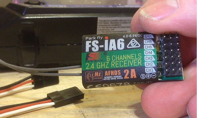
Working fairly blindly, I turned to Amazon to buy a transmitter and was shocked by prices and varieties. In my admitted ignorance, I spotted a nicely affordable 6 channel transmitter with a fantastic reviews. It was the Flysky FS-ia6 and it came with a bound receiver.
Transmitter Adjustments
When it arrived I was disappointed by the fact that both the control sticks were not centre sprung. I understand now that this is because it’s a popular transmitter with RC flyers and this static stick control is useful to them. But for me it wasn’t the intuitive, sprung-stick, back and forth motion I wanted.
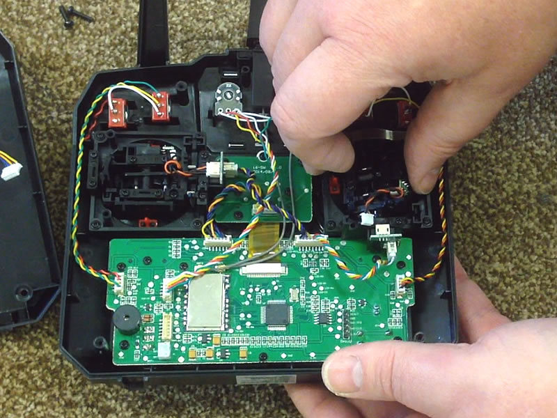
Rotating one of the sticks ninety degrees counter-clockwise (as you look at it here) is easy and allowed under the warranty. Just four screws... nothing difficult involved.
So I took the transmitter apart – not as terrifying an idea as it sounds. It doesn’t even invalidate the warranty as the instructions tell you this is possible. I rotated the left stick ninety degrees (left stick - clockwise - when looking at the face of the transmitter), put it back together and I now had the intuitive sprung action I wanted.
Next came the motor controller. These are expensive but essential. For me the Sabretooth 2x60 Dual speed controller ticked all the boxes. It handles battlebots up to 250 pounds in weight and regular bots up to 1000 lbs. Aware that my bot was already becoming a two-man lift, I realised it was pointless skimping.
No Cables... Grumble, Grumble...
Annoyingly no cables are provides to connect the receiver to the motor controller. These are what you’re looking for which I found cheaply on Amazon. These were servo extension cables. Only one end was needed, so the other was simply cut off - so this left me with a connector for the receiver and bare ends for the controller.
Right - Receiver. Left - servo extension cables necessary to plug in to the receiver
The transmitter has batteries, but the receiver needs power too and these are often powered by separate battery packs. Fortunately for me the Sabretooth has a Battery Eliminator Circuit (BEC) so batteries weren’t necessary.
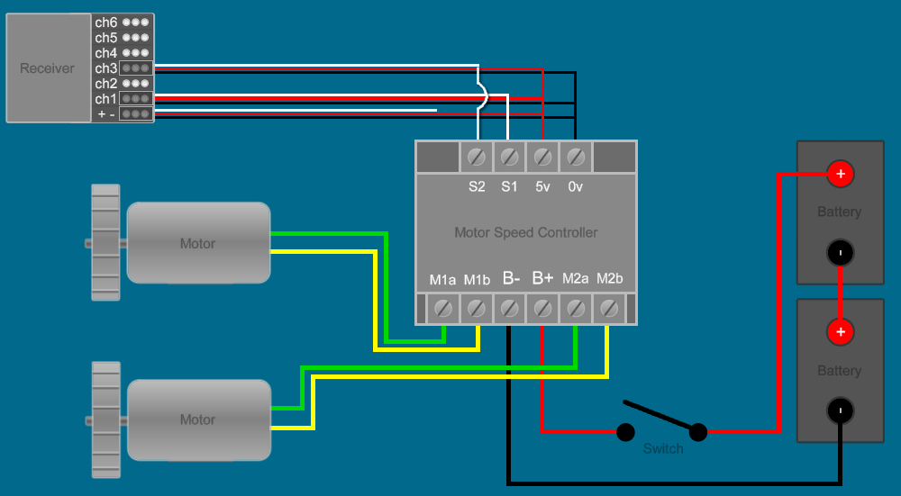
I began wiring at the Speed Controller.
We only need two wires to power the Receiver, positive and negative, so I cut away the third white (signal) wire on one lead only and marked this cable with tape to make identification easier. I then took all the red wires, bared the ends a little, and inserted these into the 5v terminal which is the positive connection.
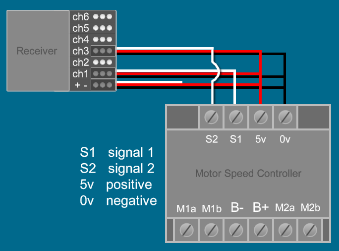
Simpler than it first looks... all the reds can be grouped and inserted into 5v (positive). All the blacks can be grouped and inserted into 0v (negative). S1 & S2 whites go to Channel 1 & 3 respectively. There is NO white signal lead to the first + - connection on the receiver.
I did the same to all the black leads and connected these to the 0v terminal which is the negative. This left two white wires and these are channel signals. As this is a Dual motor controller, it’s expecting two singles, one for each motor. So one white went to S1 and one to S2 (I can't see which is left and which is right... it would depend on which way you were looking at the vehicle, from the front or the rear).
Speed Controller DIP Switch
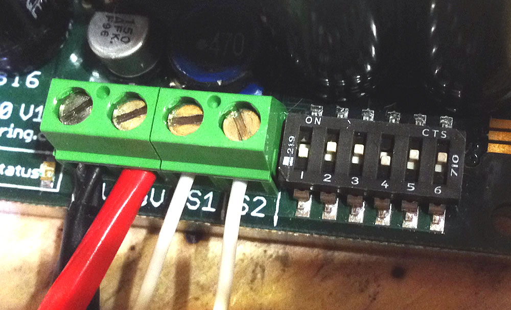
An important thing to note at this point is the DIP switch on the controller. A DIP switch is just a series of switches but these must be set correctly according to how you’re going to use the controller.
Close-up of the controller. Left - supply wires for the receiver. Right - DIP switch set to my requirements
The documentation was a little confusing but thankfully Dimension Engineering have a really helpful Wizard on their website. Simply select the motor controller you have and answer a few questions. For me it gave me this set up, which was individual track control.
I incorporated an isolation switch from the batteries to the B+ (positive) terminal of the controller. Both M1's go to one motor and M2's go to the other - polarity isn't important as the controller reverses this.
If anything, the wiring to the motor controller is even easier. The motor controller gets its power from the batteries that power the motors, in my case two car batteries. That’s a lot of juice, so I choice to isolate the batteries from the controller with a switch. As these are car batteries, I went with an Auto Battery Cut Off switch. My batteries are connected in series to give me the 24 volts the motors require and the switch simply sits between the batteries and the controller.
Looking at the controller terminals, the positive comes from the switch and the negative from the negative battery terminal. These are large terminals as thick wires are expected to handle the power.
Either side of these are the motor terminals, M1 for motor one and M2 for the other. There’s no positive or negative, just A or B as it’s largely irrelevant – the controller reverses the polarity as necessary (though it may be necessary to swap cable round depending to get things just right).
Channels
Now we come to what I feel is the only tricky bit – Channels.
As I covered earlier, a channel can be thought of as a function and in this initial set up I needed only two channels, one for the left motor and one for the right. So the transmitter needs to send appropriate channel information to the receiver.
But when you look at the transmitter, everything is a channel... the left stick UP and Down is a channel, the left stick LEFT to RIGHT is a channel, the same applies for the right stick and there's a variety of buttons and knobs. Understand my confusion?
The commands I manually input into the transmitter by pushing sticks and twiddling switches are channels and I know this transmitter has 6 channels. But which channel is which? Which is channel 1, channel 2, channel 3, et. I needed to know this information to plug in the receiver.
The problem with this transmitter is the instructions don’t tell you and it’s probably the same for many modern transmitters, but do read your instructions just in case. The reason for this is that manufacturers are allowing you to decide which channel is which and that’s to match your personal preferences and the device you’re using. You get to decide.
Got The Same As Me...?
Now if you’ve got exactly the same transmitter as me and want to steer two motors – and if you’ve turned your left stick ninety degrees clockwise, then plug the left motor servo cable to Channel One and the right to Channel Three. Then using the Transmitter Set-Up menu, select Stick Mode Number 3. That should get you rolling.
If you’ve got something different, you’ll have to figure this bit out yourself if your instruction manual lets you down. Thankfully it’s not that hard and you don’t need to be afraid. Here’s a quick walk-through…
Trial & Error
Firstly, make sure all the power is off and no batteries are connected. Then take the servo cable that was marked as a power cable and plug this in to the appropriate slots on the receiver. This is the very first slot on this model. Make sure the polarity is right!
Now if you don’t know the identity of your channels, take one of the channel servo cables and plug it into channel 1 on the receiver.
Turn on the transmitter first – in fact remember this important point...
ALWAYS turns the transmitter on FIRST and then the receiver. When you're finished, turn off the receiver and THEN the transmitter. So the Transmitter is always turned on first and turned off last. This prevents any devices doing their own thing...
Now turn on the receiver by plugging in its batteries or engaging the switch in my case. Make sure the transmitter and receiver are happily connected. I will say here, despite the manufacturer claiming my transmitter and receiver were bound, mine weren’t. Luckily it’s simple enough to do and will be covered in your instructions if you experience the same problem.
With everything on, experiment with the controls of the transmitter. Does anything work on your model? If it does, is it the correct function for the appropriate control? If not, you’ll need to unplug and try again. So turn off the receiver – leaving the transmitter on in this instance – unplug the servo cable and plug it into channel 2. Turn on the receiver and try again. Does it work now?
You can repeat this trial and error approach over all six channels until you’re transmitter and model are working how you’d expect.
This transmitter does have a set up function that allows you to swap and change these arrangements and I’ve no doubt other transmitters work in a similar way. This means that you may have to look through your transmitter options as well. My transmitter, example, has four modes – four choices of settings for the stick controls.
So, let's recap the channel selecting process...
Firstly, check the instruction manual and / or any online reference material for help
If not available, make sure to turn off the receiver and then the transmitter (in that order).
If not in place, take the BEC servo cable and connect this to the power supply for the receive (or use a battery pack if preferred), ensuring correct polarity.
Take the S1 servo cable from the motor controller and insert it into the first available channel on the receiver, ensuring correct polarity.
Turn on the transmitter and then the receiver.
Carefully check all the controls on the transmitter to see if any produce an expected response.
If not, turn off the receiver, move the servo cable to the next available position and repeat 5 & 6.
Through a process of trial and error, always ensuring the power is off between adjustments and making sure the connections are placed on their correct polarity, it's possible to determine which channels relate to the stick controls on your transmitter.
As I say, don’t be afraid to swap and change the cables... just be careful of the correct polarity and turn off between changes.
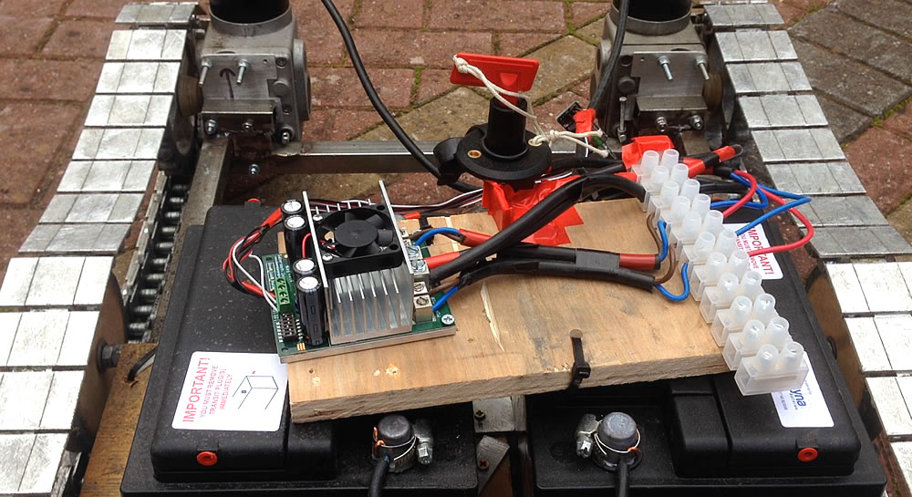
All the electronics temporarily secured. It might not look it, but everything is screwed or clamped in placed. You don't want anything falling off...
At some point you’ll get there and you’ll need to make sure everything is secured. I’ve done this on a temporary basis as I have more changes to make. The receiver does have an aerial which should be appropriately positioned for maximum range, but for me that was something to think about another day.
With everything securely fixed down in a temporary testing position, you can see it works a treat. I liked these caterpillar tracks when I built them, but they were tethered to me by long cables initially. Now I’ve got this working on radio control, I love it! And I was pleasantly surprised by how easy it was.
I hope you find this VERY BASIC introduction the radio control useful. Please remember this is the FIRST time I have every done this and if you’re in a similar position, I hope I’ve given you enough information to get you started. If you’ve got any questions or need any help, feel free to drop, me a line. I’ll certainly do my best to help.
Brilliant!!! When I found this post I went out at midnight to try... AMAZING!!
“No act of kindness, no matter how small, is ever wasted” - Aesop
If you'd like to offer a donation (and help me fund a few new projects), then please click the donate button below. Payments are handled securely by PayPal. For more information on why I have this button, click here.
Or... Become A Patron
Alternatively, if you can spare a little each month, consider becoming a Patron. Patron's make it possible for me to continue developing my YouTube Channel and my websites. Please CLICK HERE for more information.
 A few weeks ago now I built some homemade caterpillar tracks and I wanted to convert them to Radio Control but I knew NOTHING about it.