How to make an adjustable, self-tensioning Hot Wire Foam cutter
Cutting polystyrene foam is easy with a hot wire cutter. But the wire sags when it gets hot and it’s hard to get accurate, straight and nicely jointed edges. To overcome this, I’ll show you how to make an adjustable, self-tensioning, accurate and reliable hot-wire foam cutter.
Now hot wire foam cutters are ten-a-penny on YouTube and there’s dozens of sites with their own versions. However I’ve got a couple of projects coming up where an accurate, reliable foam cutter will come in very handy, and these other vids don’t seem to cover adjustability, I’ve decided to share my ideas. But in deference to the other videos, I don’t want to cover the build in too much detail, but what follows will enable a complete novice to build one from scratch. It will also help someone like me, who has an existing cutter, get greater adjustability and accuracy from it.
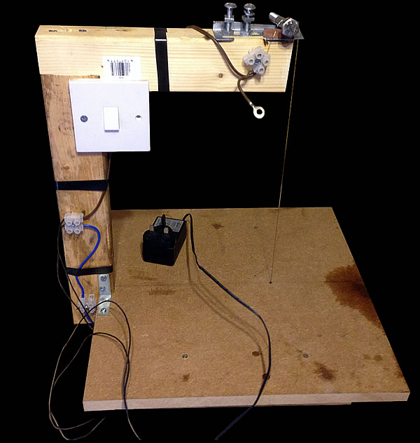
So let’s get started… here’s my cutter – and yes, I know – it doesn’t look very impressive. It’s a bit shabby and stained, but it’s a number of years old and has been assembled and disassembled dozens of times for easy storage.
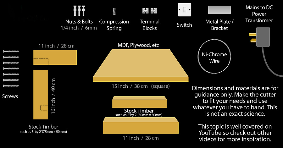
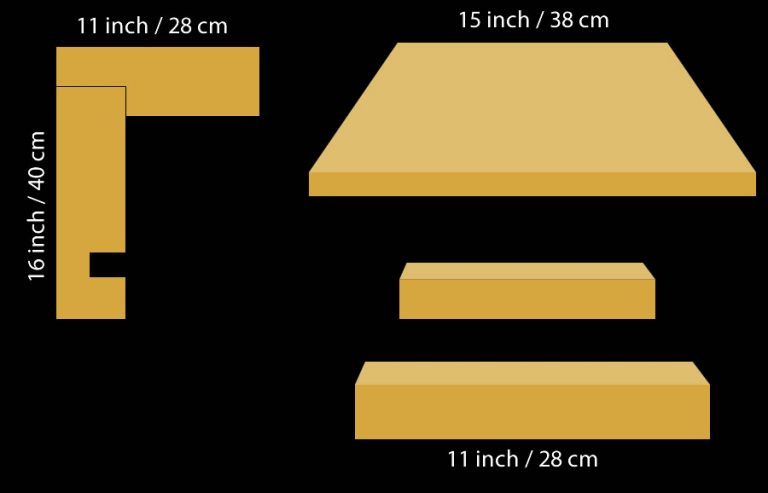
This isn’t an exact science as you can build the project very much to your own requirements, but the materials shown here and dimensions are a good guide.
Parts
As with most of my builds, I work with whatever materials I have to hand and you certainly can do the same.
wood screws, stock timber, a compression spring, nuts and bolts, terminal blocks, a switch, metal plate, mdf, a mains transformer and Ni-Chrome wire
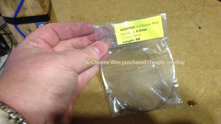
What you probably won’t have to hand is the wire… you’ll need Ni-Chrome wire but fortunately this is very cheap and easily available on eBay. I got a 4 metre length for just a few pounds and that will probably last me forever.
You’re also going to need an electrical transformer – something that reduces mains power in your neck of the woods to safe and dependable voltage. I’m going to cover the transformer in more details later.
The Build
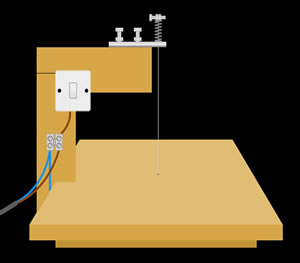
This inverted L forms the arm of the cutter that holds the hot wire. Glue and screw it for strength and ideally cut a small slot or rebate towards the bottom that’s the same height as the thickness of the board.
I used a square piece of MDF. This is nice, flat, stable material. To the bottom of this I attached a couple of wooden blocks to act as legs. It’s worth noting here, leave yourself a good clear section around the perimeter of the board to accept clamps.
It’s a simple matter to glue and screw the arm onto the board. If the rebate you cut is a good fit, this should be a doddle. You’ll see I’ve used brackets on my build, but that’s because I haven’t used glue. I like to take my cutter apart for easy storage, but ideally gluing and screwing is the way to maximise strength. However, before you glue anything, you’ll need to drill a clearance hole Ni-Chrome wire.
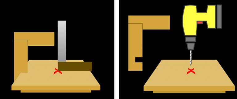
To establish where the wire will pass through the board, you can use a carpenters’ square, but if you don’t have one large enough, a simple plumb line will do just as well as long as you’re on a nice level surface. Notice that line does NOT begin at the end of the arm but actually a couple of centimetres or an inch away from the arm. This is to allow for adjustment later.
With the spot marked where the wire needs to go, using the finest drill bit you’ve probably got, drill perpendicular hole.
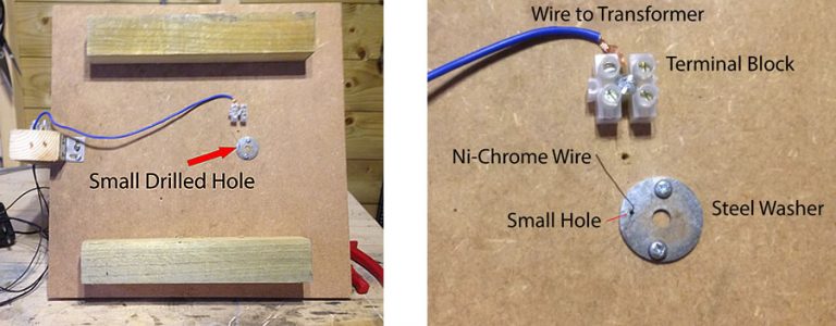
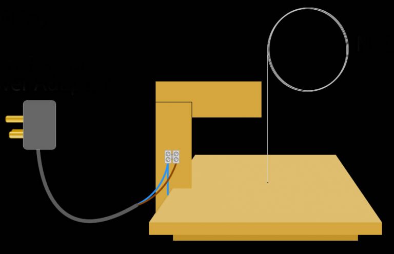
Looking at the underside of the board now, you can see that I took an ordinary steel washer and drilled a hole through it with the same drill bit. Any piece of metal will do. I just happened to have a washer. The wire passes through the face of the board, through the hole that’s been drilled and through the hole in the washer. The washer is fixed in place and this prevents the thin wire slicing through the soft MDF or even scorching it.
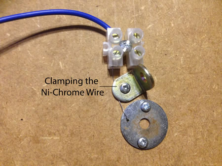
A terminal block is screwed nearby with a length of electrical wire within it. The Ni-Chrome wire is fed through the drilled hole and screwed into this. The Ni-chrome wire will be under tension and could pull free from terminal block, so I clamped the wire in place using a small metal bracket. Again anything will do for this purpose, even another washer, as long as it holds the wire firmly.
A terminal block is attached to the lower section of the arm and the electrical wire from the underside of the base connected to it. The power adapter is connected into this same terminal block. There should be two wires, a positive and a negative, and this should be low DC (direct current) voltage and NOT mains voltage. That’s critical to understand. If you get this part wrong, you could be creating something that could easily kill you.
For the cutter to work, you don’t really need to understand which of the transformer wires is positive or negative (though the positive is often red or white and the negative generally black). But this knowledge is helpful as you’ll see later.
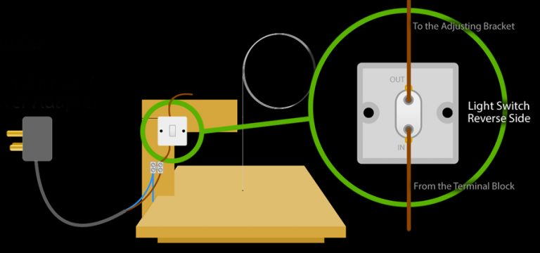
Now’s the time to add a switch and I to had an old domestic light switch to hand, so I used that. You will need a switch and you shouldn’t leave the cutter turned on if not in use as it will burn out the Ni-Chrome wire.
An electrical wire is attached to second terminal of the terminal block, that’s the brown wire on my diagram, which is NOT the wire from the base of the cutter. This brown wire simply goes into the switch and out again. You can see the reverse side of the light switch here. Typically there’s two terminals or connection points on such switches and the brown wire goes into one of these. A second brown wire is screwed into the other terminal.
This second brown cable is attached to the adjusting bracket that we’ll see in a moment. A simple ring connector can be used for this.
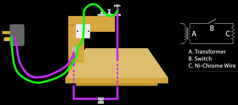
Let’s just briefly look at the electrical circuit we’ve now made.
The first part of the circuit is the Ni-Chrome wire and this passed through the board, into a terminal block, through an electrical wire and to a second terminal block. This is connected to one of the wires from the power transformer. From the transformer, power can pass through the second transformer cable, into the terminal block, into the switch, through the switch if it’s turned on, out the other side, along to out adjustable bracket and the circuit is complete.
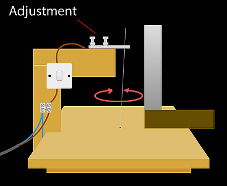
Adjustment
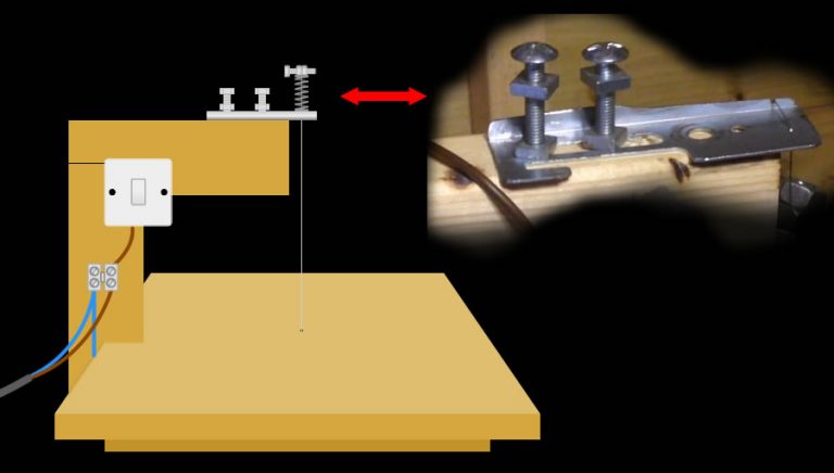
So let’s look a little more closely now at the adjustment bracket.
Now this really is simplicity itself. It’s simply a length of metal ideally, maybe four or five inches long, but crucially it has a slot running down its length. It’s through this slot that the bracket is attached to arm of the cutter. I made use of an old radiator bracket which I crudely cut down. Sorry if the aesthetics aren’t very appealing folks, but at the time of making I was more interested in functionality, and this bracket was a gift from the DIY gods.
If you can’t find something suitable and have to fabricate a bracket, make sure that the slot is about 50% wider than the width of the bolts you use to fix it in place. A loose fitting is crucial to this design. As I say, metal is ideal due to its strength and conductivity, but you could use plywood or similar – though remember you’d need to connect the switched brown wire directly to the Ni-Chrome wire.
Towards the end of this bracket, you need to drill a fine hole for the Ni-Chrome wire to pass through.
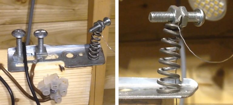
With the bracket resting on the arm, drill a couple of pilot holes with a drill bit that just a little smaller than the diameter of your bolts. You can then turn the bolts with a spanner into the timber and you should find they grip very well.
You only need to sink roughly half the length of the bolt into the arm. The other 50% holds two nuts per bolt. The lowest bolt is tightened by hand so the bracket can move, but only just. Later when you’re happy with the placement of the Ni-Chrome wire, you can fully tighten the lower nut. One of the upper nuts can clamp down on the ring connector, securing the electrical connection. This nut on nut practice is a good method of preventing unwanted loosening.
This clamp is of course the secret to the vertical adjustment. The bracket can be moved to a desired location and this in turn adjusts the vertical angle of the Ni-Chrome wire. Ideally you want this to be perfectly perpendicular to the base board, helping you achieve a nice ninety degree cut when in use.
With careful adjustment, a hell of a lot of patience and the use of a good square, a perfectly true wire is achievable.
But of course, that’s not really doable until the Ni-Chrome wire is under tension.
Tensioning Method
There’s two ways of tensioning the wire that I’ve used, Gravity and Spring. Let’s start with Gravity.
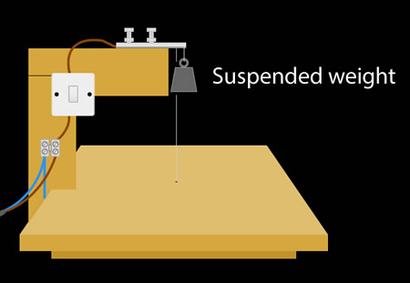
Gravity
Gravity is constant and free, so to use it we need to find a way of having gravity pull on our wire, and we can do that by attaching a weight.
A simple groove filed into the bracket allows a weight to be suspended, but care needs to be taken so that the weight doesn’t collide with the wire. Heavier is best as it will tighten the wire better, but if the weight you apply is too heavy it will snap the wire.
A tiny spot of oil on the groove point will help the weight pull nicely on the wire, but keep the main drop clean of oil otherwise it will likely smoke and smell.
This process does work and I did use it briefly. It holds the wire taught and can enable fine adjustment, but as I say, heavier is best. Personally I prefer to use a compression spring.
Spring
The spring needs to be quite strong. If you can squash it easily with your fingers, it’s probably too weak. But if you can’t budge it, it might be too strong.
The Ni-Chrome wire is simply fed through the spring and clamped at the top. I used a small bolt and a couple of nuts to achieve this. Importantly you need to compress the spring a little before tightening the nuts and clamping the wire in place. It’s fiddly and you feel like you need four extra hands, but it can be done. Once held in place, the Ni-Chrome wire should be permanently under tension from the spring. Again, not too much tension as the wire will snap, but enough that you can play a tune on it.
So there you have it, an adjustable, and self-tensioning hot-wire foam cutter. Surprisingly simple isn’t it.
Let There Be Light
And you can leave it there. But the light in my shed isn’t great and I fancied adding a light to mine.
If you’ve seen my video on homemade, custom Daytime Running Lights, you’ll remember I made use of these Eagle-Eye LED’s. These are bright and have a low power consumption. They also happily work between 6 and 12 volts and as my transformer is 12 volts, I couldn’t resist.
Wiring the LED into the circuit is easy, but you will need to know which wire is positive and which is negative. On my diagram, the brown wire is the positive connection and this is the one that passes through the switch. So that’s the perfect place to connect the positive lead of the LED, on the switched terminal of the switch. That way the light will only be on when in use. This then acts as a reminder that the power is on… helping you avoid burning out the Ni-Chrome wire if the cutter’s not in use.
The negative lead of the LED joins the blue cables in the terminal block, completing the circuit. So now, when the switch is turned on, the wire gets hot, ready for use and the light shines down on the work.
I left my LED suspended. This means I can alter its position if I need to. But if you prefer to fix yours in place, that’s down to you.
Power Supply / Mains Transformers
Now all we need to do is discuss the power transformers in a little more detail. This is probably the most difficult part for me to comfortably narrate. I’ve been making hot wire cutters since I was a kid so I have no fear of them and probably I’m much too flippant in my choice of power supply for my own good, so please DO CHECK OUT what other people say on the subject.
So what is a transformer?
As I said earlier, it’s a device to convert the mains voltage in your area to a safer, lower voltage. Here in the UK, mains voltage tends to be between 220 and 240 volts. In the US, I believe it’s around 110 volts. To be honest it doesn’t matter the national voltage is as long as you use a transformer that’s meant to be used in your region of the world. So when you source one, make sure it’s locally obtained.
I didn’t buy my transformer… well I did, but not for this project. If you’re like me you’ve probably got a draw full of these things left over from answerphones, kid’s games, etc. The device breaks, you throw it away, but somehow the transformer stays behind, and for THIS project that’s just what you want. I sorted through my box of old transformers and I found a 12 volt direct current transformer. Reading the label, it said it could handle 2 amps of current and that made it perfect for this project. And that’s the sort of thing you’re looking for… low voltage, decent current handling. If the current rating is too low, you’re transformer will burn out.
There are lots of clever people out there talking in terms of Ohms Law, resistance, ampage and voltage calculations and quite honestly, they’re right. The problem is I’m too damn casual about the whole thing to be bothered. I know that’s wrong, but at least I’m being honest with you. For me the voltage and current were okay, so I wired the whole thing together and gave it a blast. The wire didn’t glow – which it SHOULDN’T as that’s a sign of overpowering – but it cut nicely. So for me that was enough.
You can be similarly flippant if you wish, BUT just make sure your voltage is nice and low first. It doesn’t have to be direct current for a wire cutter, but these sort of transformers generally are DC as they’re used to power devices that normally run on batteries.
If your transformer fails to heat the wire enough to cut foam, you may have to shorten you wire (reducing its resistance) or you’ll to increase the voltage of your transformer.
If you’re lucky enough to have a model railway controller, this might be ideal. These usually allow you to vary voltage between zero and 12 voltage and tend to be good for around 2.5 amps. I’ve got an old Clipper Controller that’s got to be 40 years old and still going strong. But DO check the ampage of yours. If it’s not 2 amps or above, don’t risk it. You’ll probably burn it out.
Also in the description underneath this video I’ve included a few links to excellent websites that cover this topic in the sort of detail that’s ideal. If you find a good one, let me know and I’ll tack it on to the description, but for now folks that’s me done on the subject of transformers and hot wire cutters.
So that’s it folks. We’re all done.
If you have any questions, feel free to get it touch. I’m no expert, but I’m happy to offer whatever help I can.
If you want to see my YouTube video on the subject, simply click below:
“No act of kindness, no matter how small, is ever wasted” - Aesop
If you'd like to offer a donation (and help me fund a few new projects), then please click the donate button below. Payments are handled securely by PayPal. For more information on why I have this button, click here.
Or... Become A Patron
Alternatively, if you can spare a little each month, consider becoming a Patron. Patron's make it possible for me to continue developing my YouTube Channel and my websites. Please CLICK HERE for more information.