Wiring & Using the Inkbird ITC-100VH PID Temperature Controller
Whilst building an electric foundry, I made use of a PID to accurately and safely control the heat. PID stands for Proportional Integral Derivative and in simple terms is a feedback mechanism. It monitors a system and then applies a specific control as and when necessary. PIDs are often used to control speed, flow, pressure and as in this case temperature.
My controller came with a fairly basic instruction leaflet, certainly not ideal for the complete novice. Thankfully with a bit of trial and error I was able to make some sense of this as detailed below. I did find a useful YouTube video and whilst I'm not sure if it's the official product video or not, I'll include the link anyway to help anyone else looking at this item - here.
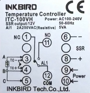
Within the instructions and on the side of the unit was a silver label depicting the suggested wiring diagram. The PID is meant to be used in conjunction with a Thermocouple and Solid State Relay.
Thermocouple
A thermocouple is an electric thermometer. They are generally made of two or more metals and as heat is applied an electromotive force is induced within these metals.
Solid State Relay
A Solid State Relay (SSR) is, like ordinary relays, an electronic switch. However, where normal relays have moving contacts, an SSR has no moving parts and therefore has a longer lifespan. They work using semiconductor devices such as thyristors and transistors rather than the traditional magnetic coils.
Circuit Set Up
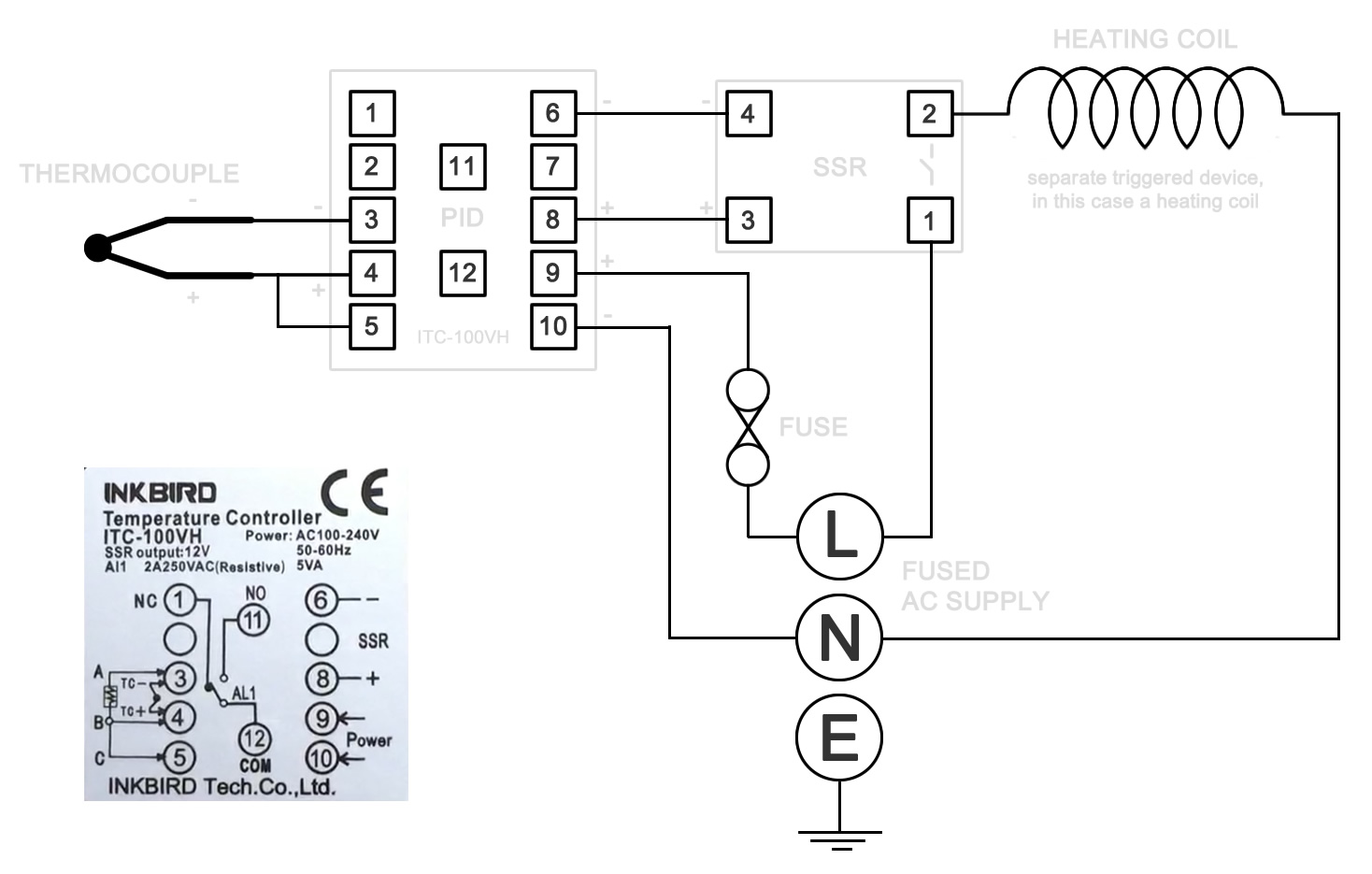
The PID has 12 numbered screw terminals and the silver label diagram shows where the SSR and the Thermocouple (TC) are wired to these. However, it's not instantly clear what to do with the SSR and how and where to power everything. Hopefully my digram below will make things a little clearer.
PID Wiring Diagram
Wiring Diagram for the Inkbird ITC-100VH PID
Please remember this diagram relates only to the Inkbird ITC-100VH PID. Other makes and models will need to be wired differently.
The power source is the mains in your neck of the woods. In my case I'm in the UK and the standard mains power is 230 volts AC. In the US I believe it's 110 volts AC. Wherever you live, you should buy the appropriately rated PID for your area. It's also worth mentioning that the standard unit of temperature in the UK is Celsius, so the PID operates in °C, though °F models are available.
Fuses
I've suggested splitting off the mains supply with two fuses though the diagram only shows one which may seem initially confusing. The PID itself requires very little power to complete its work, so a low rated fuse is appropriate here. The secondary circuit, the one that's switched on by the relay, is likely to be more demanding. In my case it's heating coil which consumes around 10 amps of current and produces 2300 Watts of power. However the whole mains supply is fused using a standard UK 13 Amp fuse and whilst this technically protects all the components, I still think it wise to protect the finer circuitry of the PID with a small fuse.
Bridge
Possibly the most confusing element of the diagram can be found between terminals 4 and 5 on the PID. Here the manufacturer tells us to bridge these, i.e. run a wire from one to the other. Whilst the first question I asked myself was 'why' I later considered that maybe the same components are used in other items sold by the same company. My advice is to not worry about this and simply bridge the terminals.
Wires
Make sure your wires are up to the task. I used a heavy-duty heat resistant flex. It's the sort of cable you might find on any quality extension lead. It's capable of handling the loads placed upon it without risk of overheating. Remember, your wire should be rated higher than your circuit. So if your circuit requires 10 amps, your wire should be able to deliver 15 amps or more. There's no upper limit to the size of the wire, but it's pointless spending good money on ridiculously overpowered cables. Just be sensible.
Remember, the outside sleeve colour of a wire does not effect the way the wire works. The sleeves are different colours to help make wiring easier (if they were all the same colour, it would be quite confusing). Though it's good practice to use specific colour wires for specific tasks (such as red for positive, blue or black for negative, etc) it's important to remember that on the inside wires are generally just copper.
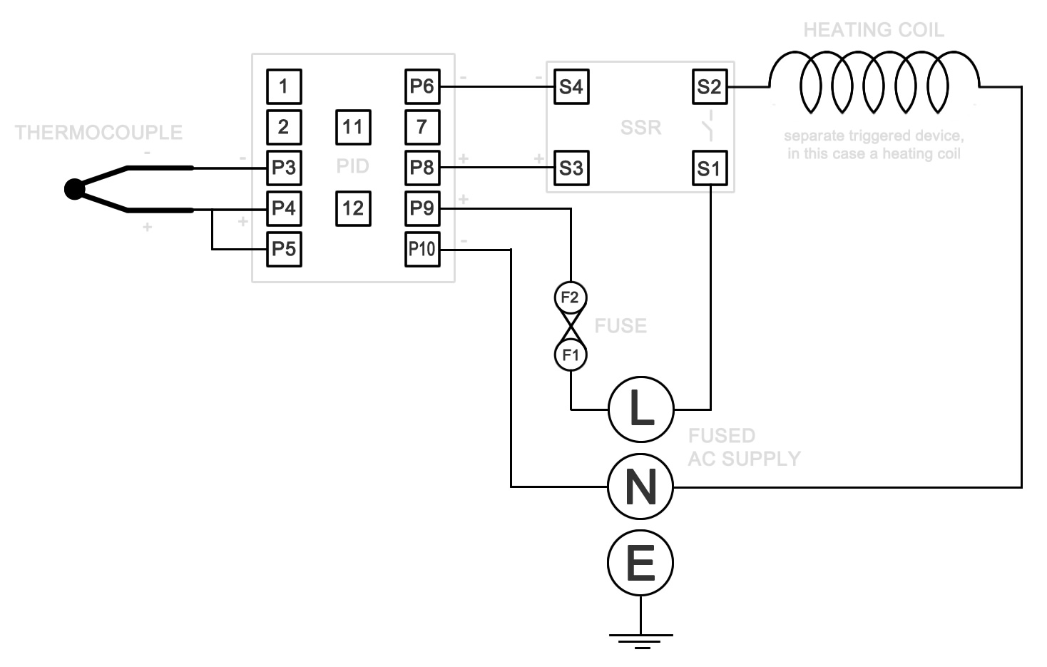
Wiring Sequence
If electronics isn't your thing, this wiring sequence might help. I've renumbered the points on the wiring diagram. Simply run a wire from point to point:
Connect the negative terminal of the thermocouple to P3
Connect the positive terminal of the thermocouple to P4
Connect P4 to P5
Connect P6 to S4
Connect P8 to S3
Connect mains Negative (N) to P10
Connect mains Negative (N) to the negative terminal of the separate device (e.g. heating coil)
Connect mains Live (L) to F1 (fuse holder input)
Connect F2 (fuse holder output) to P9
Connect mains Live (L) to S1. Ideally mains Live should be fused.
Any metal in your project might benefit from being Earthed (E)
Once the mains connections are made live, the PID should work
Initial Setup
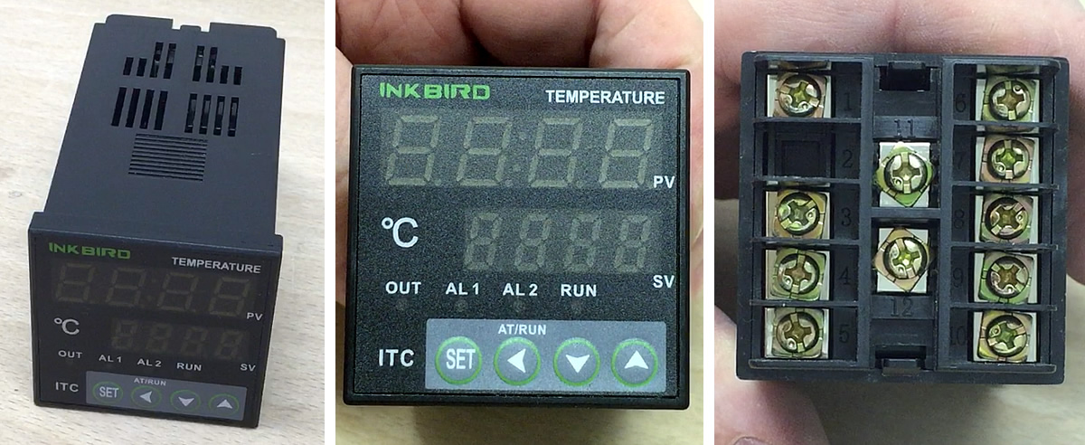
The moment the PID is turned on it shows a lot of confusing numbers that mean nothing at all. Some manual adjustment is needed.
The upper, larger red numbers should the temperature that's being picked up by the Thermocouple, or at least they should. The chances are this is wildly inaccurate. You need to manually calibrate this.
Thermocouple Adjustment
To calibrate the thermocouple, you need an accurate reading of the temperature it's supposed to be measuring. In my case, I placed a thermometer in my cold foundry and gave it a few minutes to settle. I then took the reading which at the time was 14 °C.
Thanks for this video. All the other video seem to miss a lot of the details that you mentioned..
“Remember that the happiest people are not those who are getting more, but those giving more” - H Jackson Brown JR.
If you'd like to offer a donation (and help me fund a few new projects), then please click the donate button below. Payments are handled securely by PayPal. For more information on why I have this button, click here.
Or... Become A Patron
Alternatively, if you can spare a little each month, consider becoming a Patron. Patron's make it possible for me to continue developing my YouTube Channel and my websites. Please CLICK HERE for more information.
 My controller came with a fairly basic instruction leaflet, certainly not ideal for the complete novice. Thankfully with a bit of trial and error I was able to make some sense of this as detailed below. I did find a useful